 .
.
Back To:
NARC Newsletter
From:
The Northland Antique Radio Club Newsletter
Resistance Line Cord Replacement
By Greg Farmer
This article was originally published in the Spring 2011 issue of the Northland Antique Radio Club Newsletter as a follow-up to a presentation on the various methods of replacing curtain-burner cords that was given at the club's annual Workshop.
Curtain-burner cord, heater cord, and resistance line cord all describe a type of AC line cord used to supply household current to many transformerless radios during the 1930s. These cords had a resistance wire built into them that was wired in series with the radio's tube filaments to bring the total voltage drop of the filament circuit up to the full 120 volts supplied at the plug. The resistance wire was quite warm during operation which probably contributed to these old AC cords becoming very brittle and unsafe over the years.
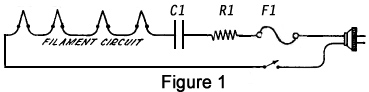
At the presentation, Steve Raymer and Bruce Wagoner briefly explained the old method of using a big hot resistor to replace the resistance wire, and the more sophisticated method of also using a diode in series with the filament string to eliminate half the voltage wave, bringing the effective voltage required to be dropped by the filaments and resistor from 120 down to 84.5 volts. But the focus of their talk was to explain how using a dropping capacitor may be the best solution in many cases. Looking at Figure 1, R1 is an optional surge limiting resistor, and fuse F1 is an optional safety modification. Calculating the value of dropping capacitor C1 is a bit complicated, so Steve mentioned that the Pavek Museum can determine this for you using their Electronic Genius program.
Steve is correct that using a dropping capacitor may be the best solution in many cases. The capacitor will behave like a resistor to AC current without getting hot, and will reduce the line voltage, but the following points should be considered:
- These radios are AC/DC radios and putting a diode or a dropping capacitor in the filament string will block DC, make it inoperative. That may not matter for most users, but needs to be noted.
- It is highly unlikely, but if a diode or capacitor shorts internally, it would blow out the filament(s).
- The exact capacitor value is critical and if it changes over time, filament voltage will change.
A few years ago, I was having trouble replacing the resistance line cord in an Emerson model 409 radio. This set has only four tubes: 78, 6F7, 38, and a 1-V rectifier, each with 6.3-volt 300ma filaments, and there is no light bulb. The total voltage drop across the four filaments is only 25.2 volts, with the other 94.8 volts dropped in the 305-ohm heater cord (shown as a resistor in Figure 2), assuming line voltage is 120 volts AC. Using the 'diode in series with a resistor' method to drop half the peak voltage only reduces the amount required to be dropped in the resistor to ((120 x 1.414) / 2) - 25.2 = 59.6 volts, and 59.6V x 0.300A = almost 18 watts. This would be a poor choice since there is no room for a 20-watt or larger hot resistor in the cabinet and adding another hot component inside there would make the radio run really hot.
The capacitor method does not generate heat. The basic circuit looks like Figure 1. Resistor R1 is an optional (will produce a little heat) surge limiter resistor that reduces surge current on cold tube filaments. The value of dropping capacitor C1 can be determined from the Pavek Museum's Electronic Genius program, or you can download a Microsoft Excel spreadsheet that will calculate it for you here.
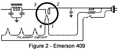
Referring to Figure 1, and looking at the schematic of the Emerson 409 in Figure 2, C1 can be determined for this example as follows:
Line voltage VIN = 120 volts and Line frequency f = 60 Hz
Total filament voltage of tubes, Vf = 4 x 6.3 = 25.2 volts
Series current of the tube string, IIN = 0.3 amps
R1 = 10v/0.3A = 33.33 ohm, if selected to drop 10 volts. It will need to dissipate 10 x 0.3 = 3 watts, so using a 10 watt size will ensure it doesn't get hot.
Effective Resistive elements Reff = Vf /IIN + R1 = 25.2/0.3 + 33.33 = 117.33 ohms
Total filament circuit input impedance. ZIN = VIN/IIN = 120/0.3 = 400 ohms
Since AC voltage across a capacitor is 90 degrees out of phase from the AC voltage across the resistive filament string, you need to do a little vector math to get the correct value for the dropping capacitor's capacitive reactance.
Capacitive Reactance, Xc = √ (ZIN2 - Reff2) = √ (4002 - 117.332) = 382.4 ohms
Capacitance = 1/(2πf Xc) = 1/(2*3.14159*60*382.4) = 6.94 mfd
A non-polarized capacitor is REQUIRED. 6.94 mfd is not a standard value. Using a 6.8 mfd 250 volt axial Mylar capacitor and working backwards through the equations, it will result in only 4.14 volts applied to each tube filament. Adding a .1 mfd capacitor in parallel, resulting in 6.9 mfd total, provides 5.78 volts to each tube filament. The exact capacitance is somewhat critical, but it is probably OK to use a slightly lower value and reduce stress on tube filaments than to use a slightly higher value that would burn the filaments more brightly.
As noted in Steve's article, radio pilot lights can be protected from surge burn out with a pair of back-to-back zener diodes rated 2 or 3 volts above the bulb voltage and a bypass resistor, all in parallel with the bulb. Add the total resistance of this circuit to the Effective Resistive elements formula above.
Now, my Emerson 409 chassis is very shallow with no space for any extra components under it. In fact, the electrolytic filter capacitors are the old type housed in a rectangular cardboard box with 3 wires coming out of it, and it is mounted above the chassis. This leaves virtually no space above the chassis either. So where to put the dropping capacitor?
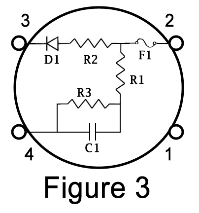
Well, here's an idea that works pretty slick. Figure 2 shows the rectifier circuit in the model 409. It uses a 1-V rectifier tube and the resistor shown is actually the line cord resistance connected directly between the plug and the rectifier's pin 1 filament connection. Using a 4-pin tube base identical to the one on the 1-V rectifier tube and soldering parts into it as shown in Figure 3, gives you a solid-state rectifier that when simply plugged into the model 409's rectifier socket, with no modification to the original radio wiring, will also disconnect the resistance wire from the circuit at pin 1, add the dropping capacitor and associated parts, and also adds a safety fuse!
Looking at other AC-DC radio schematics, this basic method should work for most of them if appropriate component values are used. It is critical that the rectifier tube must be first in the filament string, as most are.
For the model 409 example and looking at Figure 3, surge limiter R1 was already determined above to be 33 ohms, 10 watts. Recalculating the value of dropping capacitor C1 with Vf = 18.9 volts for the 3 remaining 6.3-volt tube filaments yields C1 = 6.83 mfd. Using my 6.8 mfd capacitor would result in about 5.5 volts on each of the 3 tube filaments, but adding a .03 mfd capacitor in parallel brings each of the 3 tube filaments up to 6.3 volts. R3 is a 100K ohm, 1 watt resistor that will discharge the capacitor quickly when the radio is switched off. D1 is a common 1N4007 1-amp 1000PIV silicon diode. R2 is a dropping resistor required since the resistance of a diode is much less than that of the 1-V tube. The value of R2 needs to be determined depending on the B+ voltage and current requirements of the radio. A 1-amp slow-blow fuse should work fine for fuse F1 in most cases. I soldered the fuse directly into the 4-pin socket rather than use a fuse connector to reduce size of the completed assembly.
While this solid-state rectifier can simply replace the original rectifier with no wiring modifications, it is strongly advised to replace the original deteriorated AC cord with a new two-wire AC cord with a polarized plug. You may have noticed that this model 409 chassis ties one side of the AC cord directly to the chassis, so adding a polarized plug is an especially important improvement to ensure the safety of anyone operating the radio.
Copyright 2026. All rights reserved.
The Northland Antique Radio Club